

How To Draw A Lan Network Diagram
How to Depict Network Diagrams
A network diagram is a way to illustrate the relationships among components. When drawing a network diagram, you'll need three things: symbols representing those components, connecting lines, and a way to clearly characterization them.
SmartDraw gives you all three. It includes a big library of symbols representing servers, computers, routers and more. Labels are simple to add. Information technology besides allows you to easily and intuitively describe your network diagram.
This short video provides a quick overview of how to describe a network diagram with SmartDraw.
Getting Started
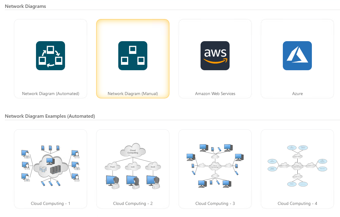
To start drawing, open a Network Diagram template from the Template Browser.
This template will open up with a set of relevant symbols and controls.
For most network diagrams, we recommend starting with the "manual" network diagram template, which volition let you draw lines and easily connect new shapes at the finish in a flexible way.
Finding the Correct Device
Any network diagram template opens with a few libraries of commonly used symbols docked side by side to in the SmartPanel.
You can discover additional devices and symbols in SmartDraw using the Search Symbols command at the top of the SmartPanel.
Clicking on Search Symbols, will open the Symbols tab with a search field. Type in the name of the device you're looking for.
One time the search is completed, the results will be organized past the libraries they're contained in. You can click on the 3 dots next to the library's proper name to either add just the symbols that match your search or the entire library.
Y'all can as well pin all the symbols institute with your query using the star icon side by side to the search field.
This panel works like the SmartPanel and you can drag-and-driblet symbols straight from this view or you can dock some of your search results for quicker access subsequently.

Adding a Device to Your Drawing
Once a library is open, you lot can click on whatsoever device and postage it or drag and drop it to the drawing area.

Connecting Devices
In one case you have added a network symbol to your cartoon, you can add together a new connected symbol by simply clicking on i of the yellow dots on the perimeter of the symbol, drawing a line, and choosing a new symbol from the auto-prompt.

Connection Points
When you link to a device, black dots chosen Connectedness Points appear on its edges. These points show the places where the device can be linked to a line or to another device. Yous tin accommodate the positions of these connexion points by selecting the symbol and clicking on "Connection Points" in the Blueprint tab.
In the dialog that pops upwardly you lot'll see your electric current Connexion Points appear effectually the preview of the device. Click on a connectedness point and elevate it to the desired position. By moving the connection points you can control where lines volition link to this detail device. For example, you tin can evidence a cable linked to a specific port past connecting a line to a connectedness point that you have positioned on top of the port.

Calculation a Text Characterization to a Device
SmartDraw objects can automatically accept text labels associated with them. To put a text label on a device in your drawing, double-click on the device in your cartoon and merely type the label. By default, the text label volition automatically go below the object.
To change the location of the text characterization relative to the object, open the Edit Symbol dialog box again from the library window. Yous can set whether your text appears below, above, or inside the object. When you choose to place text inside the object, you can set the text entry area by adjusting the four margin lines as shown below.
You can now type device names, details, descriptions inside the object for a professional person await. The text characterization stays with the device when you movement it. To edit it, merely double click on the text.

Changing the Line Shape
When you describe a line using the yellowish dots at the perimeter of network symbols, you'll be drawing a segmented line by default.
The segmented line attaches itself perpendicularly to both objects, and information technology flows betwixt them using the fewest possible number of segments and 90-degree turns. If you lot move one of the objects, the segmented line adjusts itself to remain attached and perpendicular at all times.
You can conform the length and spacing of segments by moving the square adjustment handles located on each segment.
Y'all can select whatever line connecting two shapes and change its shape using the Line Shape dropdown on the SmartPanel.
You can also use arcs or curved lines to connect your shapes. If you lot are using an arc, yous can suit the arc's degree of curvature with the special selection handle at its centre.
Curved lines are segmented lines with rounded corners. They follow the same rules equally segmented lines.

Using Automatic Connectors to Depict Bus Topologies
SmartDraw'south automatic connector allows you to connect several computers in evenly spaced patterns. The automated connector is great for drawing bus or linear topologies, but it may be fifty-fifty more useful for star networks, to automatically connect dozens of workstations to a central hub or switch without drawing all the individual connecting lines.
To use an automated connector in your network diagram, start with the Network Diagram (Automated) template. Then use the "Add together Right", "Add Left" buttons in the Network Diagram template'southward SmartPanel on the left.
Now when you remove or move a symbol, the residue of the arrangement will automatically heal and accommodate.

Creating a Custom Library of Symbols
If you imported a symbol from somewhere else or drew your own, you tin create your own custom library of images.
To create a library in SmartDraw, click on the hamburger menu at the top of the docked Symbols department, and select "Add together New Custom Library."
Next, name the library.
The new library will be immediately docked adjacent to your drawing.

To add a device to your new library, drag the device onto the library window until you see the add library cursor, then release the device with the mouse.

Before your device is added to the library, yous'll take the opportunity to give information technology a proper name and set how it will be alter colors when added to a diagram.
The new device symbol will appear as a push in your library window.

Importing Visio Stencils
In add-on to creating one off custom symbols and custom libraries, you tin also import any existing symbols you may have stored as Visio stencils.
To import Visio stencils, click on the the More tab in the SmartPanel, and select "Import Visio Stencils."
You'll be able to scan for a Visio stencil file on your desktop.


Source: https://www.smartdraw.com/network-diagram/how-to-draw-network-diagrams.htm
Posted by: edwardscompossides.blogspot.com
0 Response to "How To Draw A Lan Network Diagram"
Post a Comment